If you ended up here it’s because you’re a subscriber or a web search led you here. Great.
Tasmota is likely on your radar already and you’re trying to flash a Tuya-based ESP device with Tasmota.
Easy way
The easy way, whenever it works, is great. It only takes a few minutes. Use a recent Ubuntu or any of the alternatives described on the tuya-convert project page. Make sure to have it install all prerequisites and after that execute start_flash.sh and read as well as follow the instructions given.
The part which I accidentally forgot for one out of four SP1 plugs was to connect some other device to the vtrust-flash access point prior to attempting flashing the smart plug. The device ended up in some strange state from which I was unable to recover it. Which brought me to the hard way.
Hard way
That was still of a surprisingly moderate difficulty, but definitely more challenging overall.
All my steps I attempted from a Ubuntu 20.04.
Prerequisites:
- Unplug the smart plug from mains!
- Soldering iron
- A few jumper cables
- Any method which can be used to flash an ESP (another ESP usually works fine), I ended up using the FTDI-based DSD Tech SH-U09C5 USB-to-TTL UART converter cable which can be configured for 3.3 V via a jumper ((Before that I was failing at getting my Bus Pirate into UART bridge mode, oh well.))
- Triangular bit for the triangle screws of the casing
Opening up the casing was easy. The board of my Gosund SP1 showed SP1-C_V2.4 with a timestamp 20181101 as the hardware revision. By gently pulling the clamps on either side you can unlock the main PCB from its fixed position. Be careful, though. The cables normally connected to mains are soldered and you can only move the main PCB so much.
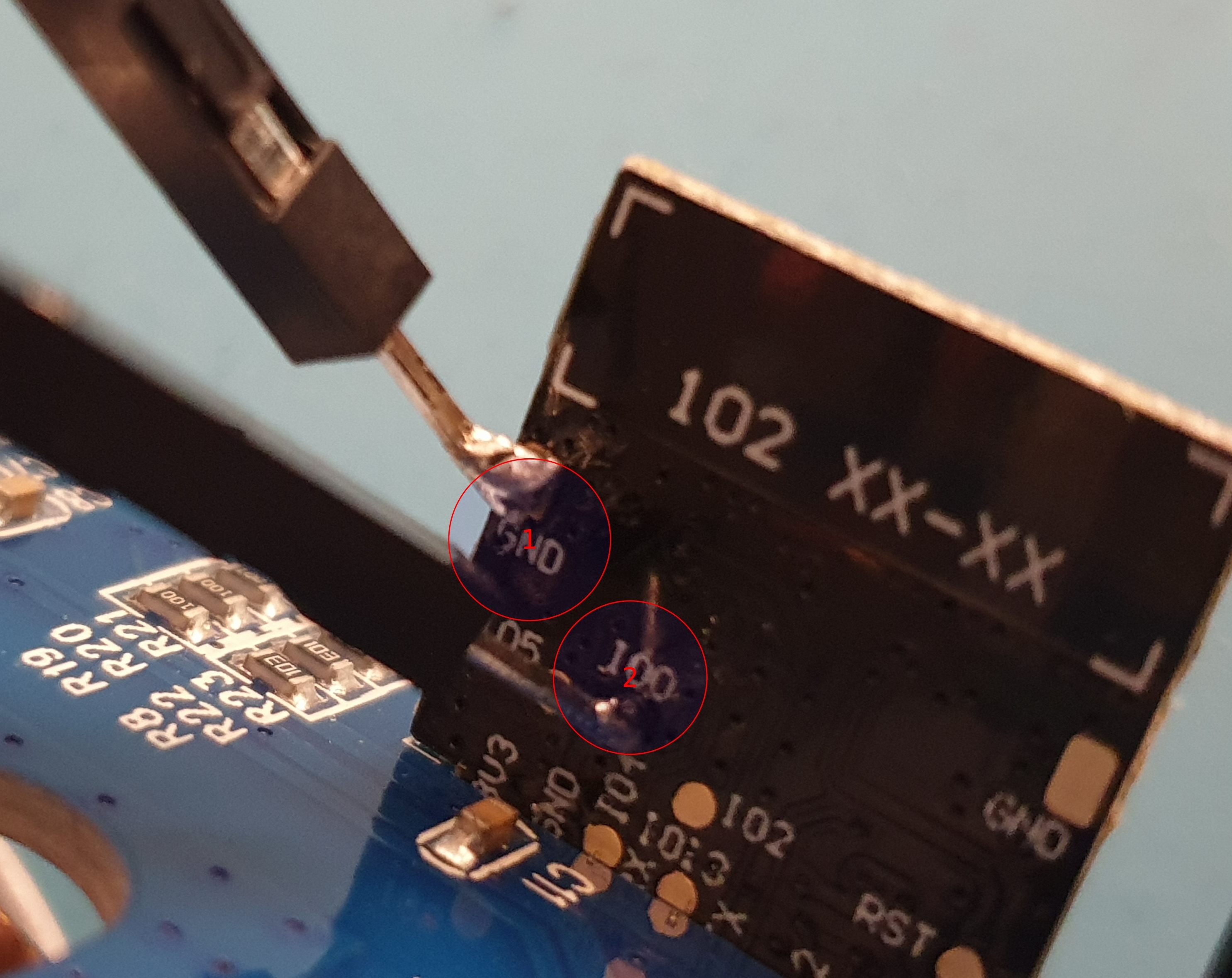
So first I shorted the GND and IO0 soldering pads on the back of the ESP board using a jumper wire, which I soldered on. Not pretty but does the job.
- Soldering pad for GND with a jumper wire soldered to it
- Soldering pad for IO0 the other end of the same jumper wire soldered to it
Make sure to tin your soldering tip as well as the ends of the jumper cable. Both are shorted with the same jumper cable, which is apparently necessary to get the device into a mode where it can be flashed. According to the Tasmota documentation you should also be able to simply keep the button pressed while powering on, which should pull the IO0 pin to ground also. I didn’t try that, though.
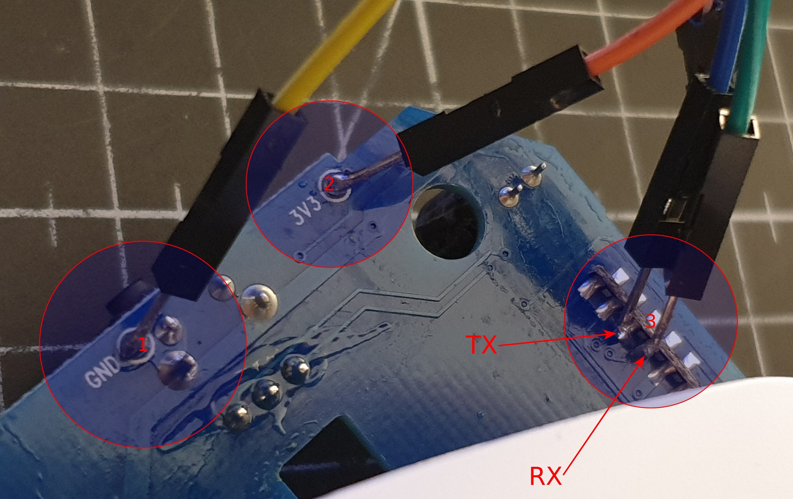
Then on the back of the main PCB I tinned the GND and 3V3 soldering pads and connected them to respective pins of the USB-to-TTL UART converter cable. Then below the base of the soldered on ESP board, I soldered the jumper wires to the middle two contacts.
- Cable soldered to GND soldering pad; this goes to the GND pin of the FTDI adapter
- Cable soldered to 3V3 (3.3 Volt) soldering pad; this goes to the VCC pin of the FTDI adapter
- Blue cable soldered to pin 3 (left-to-right for the inner row of contacts) and green cable soldered to pin 4
- Remember TX (transmit) on one side gets connected to RX (receive) on the other. So the blue cable connects to the RX (or RXD) pin of the FTDI adapter, while the green cable connects to the TX (or TXD) pin on the FTDI adapter!
- The two labels TX and RX are the labels as they would usually be printed onto the PCB, but as you can see it isn’t labeled in these positions.
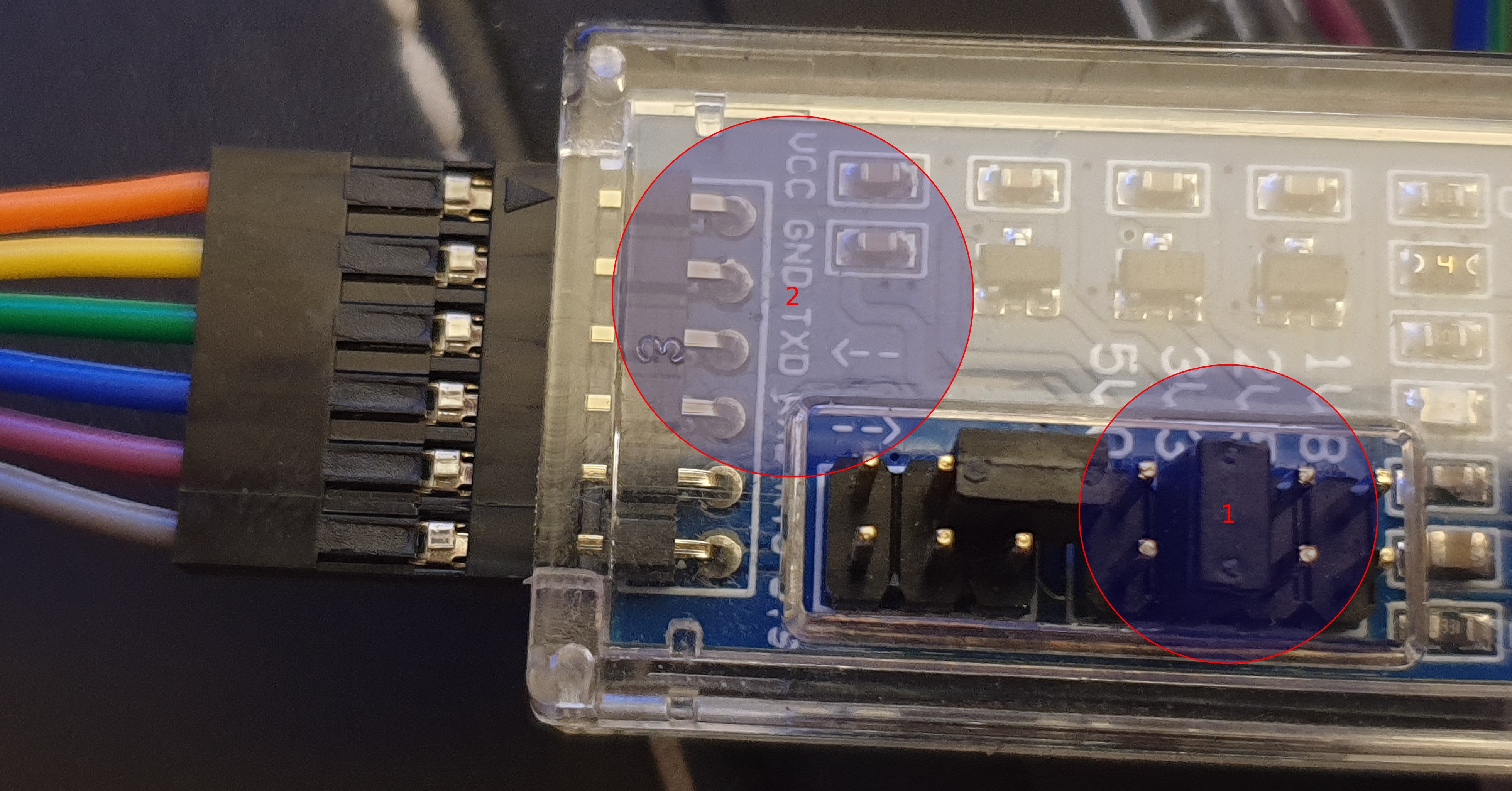
Here are the color-coded cables connected to the FTDI adapter for reference.
- This jumper can be used to set the voltage level and 3.3 Volt is exactly what we want for this case
- Only VCC, GND, TXD and RXD pins are in use, the “bottom” two pins are not connected to the smart plug in any way!
After finishing the soldering job it was time to attempt to flash the device. First I used esptool (version 2.8) which comes with Ubuntu 20.04 and failed. The erase_flash command would always fail telling me that it wasn’t supported.
Erasing flash (this may take a while)...
A fatal error occurred: ESP8266 ROM does not support function erase_flash.
I was puzzled. So I researched the topic a bit and ruled out the first issue. Apparently older packaged versions of esptool, namely version 2.1, also exhibited this behavior. But I was using version 2.8 which supposedly works. After some more searching I concluded that the ESP must be in boot loader mode, which means the erase_flash command would indeed not be supported. I needed some stub. This is when I discovered Tasmotizer which I swiftly conjured up onto my machine using python -m pip install -U tasmotizer ((their project site gives other options, especially for Windows)). Either way, because this application seems to be PyQt5-based, it worked out of the box even on Linux and it seemed to use the esptool under the hood, as I could witness from the terminal output after starting it. Either way, with Tasmotizer it was a breeze, since it evidently brought the required stub to allow flashing.
esptool.py v2.8

Serial port /dev/ttyUSB0

Connecting....

Chip is ESP8285

Features: WiFi, Embedded Flash

Crystal is 26MHz

Uploading stub...

Running stub...

Stub running...

Configuring flash size...

Auto-detected Flash size: 1MB

Erasing flash (this may take a while)...

Chip erase completed successfully in 0.9s

Compressed 601904 bytes to 429778...

Wrote 601904 bytes (429778 compressed) at 0x00000000 in 38.2 seconds (effective 126.0 kbit/s)...

Hash of data verified.
Leaving...
Hard resetting via RTS pin...
After that I had to remove the smart plug from the FTDI adapter and first of all desolder the jumper wire used to short GND and IO0 (putting the device in some flash mode). After that I powered it back on before closing the casing and I got the usual tasmota-.... WiFi AP available and was able to configure the device to connect to my own WiFi.
Once I confirmed everything worked as expected, I simply desoldered all the other wires I had soldered on and closed the casing, first only fastening two of the screws. Plugging it into mains confirmed that it worked, so I finished fastening the other two screws and the device works now like the other three.
// Oliver


